In AUTOSAR port-based sender-receiver (S-R) communication, AUTOSAR software components read and write data to other components or services. To implement S-R communication, AUTOSAR software components define:
In Simulink ® , you can:
Note If you are using a Simulink data dictionary to store interfaces, you must configure these interfaces using either the Architectural Data Editor or the relevant programmatic interfaces, Simulink.dictionary.ArchitecturalData .
For an example modeling sender-receiver communication using Simulink bus ports, see Configure AUTOSAR Ports By Using Simulink Bus Ports.
This procedure outlines the general workflow for modeling AUTOSAR sender and receiver components in Simulink. This example assumes that a Simulink data dictionary is not used to store interfaces. If you are using a Simulink data dictionary to store interfaces, you must configure these interfaces using either the Architectural Data Editor or the relevant programmatic interfaces, Simulink.dictionary.ArchitecturalData .
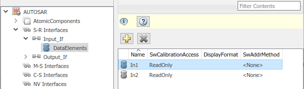
To create an S-R interface and ports in Simulink:
![]()


AUTOSAR Release 4.1 introduced the AUTOSAR provide-require port ( PRPort ). Modeling an AUTOSAR PRPort involves using a Simulink inport and outport pair with matching data type, dimension, and signal type. You can associate a PRPort with a sender-receiver (S-R) interface or a nonvolatile (NV) data interface.
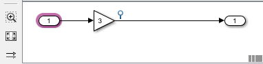
To configure an AUTOSAR PRPort for S-R communication in Simulink:
![]()


![]()
Alternatively , you can programmatically add and map a PRPort port using AUTOSAR property and map functions. The following example adds an AUTOSAR PRPort (sender-receiver port) and then maps it to a Simulink inport and outport pair.
hModel = 'my_autosar_expfcns'; open_system(hModel) arProps = autosar.api.getAUTOSARProperties(hModel); swcPath = find(arProps,[],'AtomicComponent')
swcPath = 'ASWC
add(arProps,'ASWC','SenderReceiverPorts','PRPort','Interface','Interface1') prportPath = find(arProps,[],'DataSenderReceiverPort')
prportPath = 'ASWC/PRPort'
slMap = autosar.api.getSimulinkMapping(hModel); mapInport(slMap,'RPort_DE1','PRPort','DE1','ImplicitReceive') mapOutport(slMap,'PPort_DE1','PRPort','DE1','ImplicitSend') [arPortName,arDataElementName,arDataAccessMode] = getOutport(slMap,'PPort_DE1')
arPortName = PRPort arDataElementName = DE1 arDataAccessMode = ImplicitSend
AUTOSAR defines quality-of-service attributes, such as ErrorStatus and IsUpdated , for sender-receiver interfaces. The IsUpdated attribute allows an AUTOSAR explicit receiver to detect whether a receiver port data element has received data since the last read occurred. When data is idle, the receiver can save computational resources.
For the sender, the AUTOSAR Runtime Environment (RTE) sets the status of an update flag, indicating whether the data element has been written. The receiver calls the Rte_IsUpdated_ Port _ Element API, which reads the update flag and returns a value indicating whether the data element has been updated since the last read.
In Simulink, you can:
To model IsUpdated service in Simulink, you pair an inport that is configured for ExplicitReceive data access with a new inport configured for IsUpdated data access. To configure an AUTOSAR receiver port for IsUpdated service:


![]()
if (Rte_IsUpdated_Input_DE1()) < … Rte_Read_Input_DE1(&tmp); … >The exported ARXML code contains the ENABLE-UPDATE setting true for the AUTOSAR receiver port.
Input … /pkg/if/Input/DE1 …true …
The AUTOSAR standard defines an invalidation mechanism for AUTOSAR data elements used in sender-receiver (S-R) communication. A sender component can notify a downstream receiver component that data in a sender port is invalid. Each S-R data element can have an invalidation policy. In Simulink, you can:
For each S-R data element, you can set the Signal Invalidation block parameter Signal invalidation policy to Keep , Replace , or DontInvalidate . If an input data value is invalid (invalidation control flag is true ), the resulting action is determined by the value of Signal invalidation policy:

To configure an invalidation policy for an AUTOSAR S-R data element in Simulink:


![]()
/* SignalInvalidation: '/Signal Invalidation' incorporates: * Inport: '/In2' */ if (!Rte_IRead_Runnable_Step_RPort2_InElem2()) < /* Outport: '/Out' */ (void) Rte_Write_PPort_OutElem(mSignalInvalidation_B.Gain); > else < Rte_Invalidate_PPort_OutElem(); >The exported ARXML code contains the invalidation setting for the data element.
/pkg/if/Out/OutElem KEEP
AUTOSAR end-to-end (E2E) protection for sender and receiver ports is based on the E2E library. E2E is a C library that you use to transmit data securely between AUTOSAR components. End-to-end protection adds additional information to an outbound data packet. The component receiving the packet can then verify independently that the received data packet matches the sent packet. Potentially, the receiving component can detect errors and take action.
For easier integration of AUTOSAR generated code with AUTOSAR E2E solutions, Embedded Coder ® supports AUTOSAR E2E protection. In Simulink, you can:
Simulink supports using either the E2E Transformer method or the E2E Protection Wrapper to implement end-to-end protection in the generated code. You can retrieve which end-to-end protection method is configured by using the function getDataDefaults . You set the end-to-end protection method by using the function setDataDefaults .
Configure E2E protection for individual AUTOSAR sender and receiver ports that use explicit write and read data access modes. When you change the data access mode of an AUTOSAR port from explicit write to end-to-end write, or from explicit read to end-to-end read.
| Generated Item | E2E Protection Wrapper | E2E Transformer |
|---|---|---|
| Generated Code for Initialization | Calls E2EPW_ReadInit_ or E2EPW_WriteInit_ | None |
| Generated Code for Function Signature | Uses uint32 E2EPW_Read_(data*) or (void) E2EPW_Write_ | Uses uint8 Rte_Read_(data*, Rte_TransformerError*) or (void)Rte_Write_(data, Rte_TransformerError*) |
| ARXML Exporter for Receiver and Sender COM-SPECs | Generates property USES-END-TO-END-PROTECTION with value true | Generates property USES-END-TO-END-PROTECTION with value true |
| ARXML Exporter for Receiver and Sender API Extensions PORT-API-OPTIONS | None | Generates property ERROR-HANDLING with value TRANSFORMER-ERROR-HANDLING |
To configure an AUTOSAR sender or receiver port for E2E transformer protection:
slMap = autosar.api.getSimulinkMapping(modelName); setDataDefaults(slMap, 'InportsOutports', . 'EndToEndProtectionMethod', 'TransformerError');


![]()
void Runnable(void) < Rte_TransformerError transformerError_Input; float64 tmpRead; … /* Inport: '/Input' */ Rte_Read_RPort_InputDE(&tmpRead, &transformerError_Input); … /* Outport: '/Output'. */ (void) Rte_Write_PPort_OutputDE(data, &transformerError_Input); … >The generated header file Rte_ model .h contains the transformer error declaration.
/* Transformer Classes */ typedef enum < RTE_TRANSFORMER_UNSPECIFIED = 0x00, RTE_TRANSFORMER_SERIALIZER = 0x01, RTE_TRANSFORMER_SAFETY = 0x02, RTE_TRANSFORMER_SECURITY = 0x03, RTE_TRANSFORMER_CUSTOM = 0xff >Rte_TransformerClass; typedef uint8 Rte_TransformerErrorCode; typedef struct < Rte_TransformerErrorCode errorCode; Rte_TransformerClass transformerClass; >Rte_TransformerError;The exported ARXML code contains the E2E settings for the AUTOSAR receiver and sender ports.
… …true … …true …… TRANSFORMER-ERROR-HANDLING /pkg/swc/ASWC/RPort … TRANSFORMER-ERROR-HANDLING /pkg/swc/ASWC/PPort
To configure an AUTOSAR sender or receiver port for E2E wrapper protection:
slMap = autosar.api.getSimulinkMapping(modelName); setDataDefaults(slMap, 'InportsOutports', . 'EndToEndProtectionMethod', 'ProtectionWrapper');
![]()
void Runnable_Step(void) < … /* Inport: '/Input' */ E2EPW_Read_RPort_InputDE(…); … /* Outport: '/Output'. */ (void) E2EPW_Write_PPort_OutputDE(…); … > … void Runnable_Init(void) < … /* End-to-End (E2E) initialization */ E2EPW_ReadInit_RPort_InputDE(); E2EPW_WriteInit_PPort_OutputDE(); … >The exported ARXML code contains the E2E settings for the AUTOSAR receiver and sender ports.
…true … …true …
In AUTOSAR sender-receiver communication between software components, the Runtime Environment (RTE) raises a DataReceiveErrorEvent when the communication layer reports an error in data reception by the receiver component. For example. the event can indicate that the sender component failed to reply within an AliveTimeout limit, or that the sender component sent invalid data.
Embedded Coder supports creating DataReceiveErrorEvent s in AUTOSAR receiver components. In Simulink, you can:
You should configure a DataReceiveErrorEvent for an AUTOSAR receiver port that uses ImplicitReceive , ExplicitReceive , or EndToEndRead data access mode.
To configure an AUTOSAR receiver port for a DataReceiveErrorEvent :


![]()

arProps = autosar.api.getAUTOSARProperties(mdlname); add(arProps,ibQName,'Events','DRE_Evt'. 'Category','DataReceiveErrorEvent','Trigger','rPort.DE1'. 'StartOnEvent',runnableQName);
. DRE_Evt /Root/mDemoModel_swc/ReceivingASWC/IB/Run_ErrorHandling /Root/mDemoModel_swc/ReceivingASWC/rPort /Root/Interfaces/In/DE . Run_ErrorHandling 0 false .Run_ErrorHandling
In AUTOSAR software components, a sender or receiver port optionally can specify a communication specification (ComSpec). ComSpecs describe additional communication requirements for port data.
To model AUTOSAR sender and receiver ComSpecs in Simulink, you can:
For example, if you create an AUTOSAR receiver port in Simulink, you use the Code Mappings editor to map a Simulink inport to the AUTOSAR receiver port and an S-R data element. You can then select the port and specify its ComSpec attributes.

Here are the properties for a queued receiver port.

If you import or create an AUTOSAR receiver port, you can use the AUTOSAR Dictionary to view and edit the ComSpec attributes of the mapped S-R data elements in the AUTOSAR port.

To programmatically modify ComSpec attributes of an AUTOSAR port, use the AUTOSAR property function set . For example:
hModel = 'autosar_swc'; openExample(hModel); arProps = autosar.api.getAUTOSARProperties(hModel); % Find ComSpec path portPath = find(arProps,[],'DataReceiverPort','PathType','FullyQualified'); ifPath = find(arProps,[],'SenderReceiverInterface','Name','Input_If','PathType','FullyQualified'); dataElementPath = find(arProps,ifPath,'FlowData','Name','In1','PathType','FullyQualified'); infoPath = find(arProps,portPath,'PortInfo'. 'PathType','FullyQualified','DataElements',dataElementPath); comSpecPath = find(arProps,infoPath,'PortComSpec','PathType','FullyQualified'); % Set ComSpec attributes set(arProps,comSpecPath,'AliveTimeout',30,'HandleNeverReceived',true,'InitValue',1); get(arProps,comSpecPath,'AliveTimeout') get(arProps,comSpecPath,'HandleNeverReceived') get(arProps,comSpecPath,'InitValue')
To set the QueueLength attribute for a queued receiver port:
set(arProps,comSpecPath,'QueueLength',10);
When you generate code for an AUTOSAR model that specifies ComSpec attributes, the exported ARXML port descriptions include the ComSpec attribute values.
. ReceivePort /Company/Powertrain/Interfaces/Input_If/In1 .30 true .DefaultInitValue_Double_1 /Company/Powertrain/Constants/DefaultInitValue_Double_1 DefaultInitValue_Double_1 DefaultInitValue_Double_1 1